Welcome to UNIHIKER M10 Documentation
Unleash your imagination and embark on a new journey with UNIHIKER M10.
Note
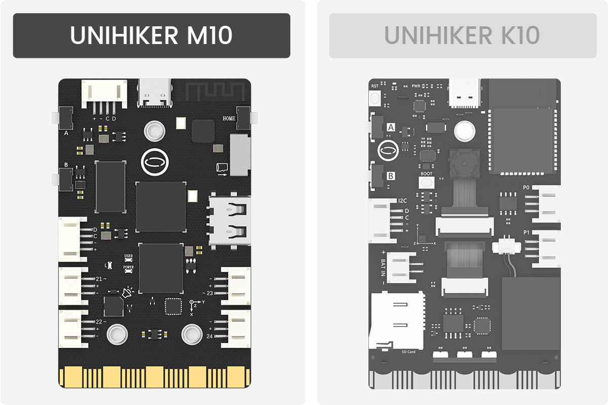
The UNIHIKER M10 and K10 can be distinguished simply by the presence or absence of a camera and USB-A port on the back.
-
Getting Started
Essential for Beginners
Jupyter Notebook | Mind+ | VS Code | Python IDLE | Terminal Tool | Thonny
-
Examples
Get Started Quickly Through Projects
Python Coding | Graphical Coding
-
Language Reference
Software Library and API Documentation
-
Hardware Reference
Hardware-Related Information
Components | System Framework | Specification | Overview | Dimension | SVG & 3D File